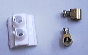
Right front power window mechanism, right rear window regulator mechanism.


Being used to (spoiled by?) 4 power windows in my BX I wanted the same in my Xantia. Hard to find at the breakers around here though. On the other hand, almost all xantias have power windows in front. I probably would have found it if I searched harder, but I decided on a different approach.
So I was wondering - do the front power window mechanisms fit the rear doors? The trim panels look very much alike and so do the doors themselves, internally. So I went to the breakers, pulled a front pwr window mechanism and tried to fit it to the rear of same car. No go. I bought both mechanisms anyway, thinking I could probably make it work. I took pictures of both, to show the differences. Note that the motor seems backwards but that's how it's supposed to be. It is also probably the reason one of the cables (that I didn't need anyway) was kinked - a design flaw?
Right front power window mechanism, right rear window regulator mechanism.
Both use bowden cables (like your throttle cable and bicycle brakes) to pull the window up and down. The glass is attached to the mechanism at only one point, to the white plastic slider that goes up and down the guide rail. That rail is 18mm shorter in the rear doors than it is in the front doors, has different mounting points and is placed closer to the motor (shorter cables). For the motor itself, the mount points in the doors are all the same front and rear. Fortunately it's possible to put the rear rail on a front window motor and shorten the cables, so all you need is a pair of easy to find front window mechanisms to make your rears electric as well. As I said the cables are simple like bicycle brakes, you just need to be precise about cutting them to exactly the right length and then put reliable new stops on them that fit the guides without hitting the ends.
Perhaps you could shorten and modify a front mechanism to make it fit in the rear as a whole, but since you'll be throwing the standard hand mechanisms out anyway, I thought it would be better and easier to transfer the outer cables and rail from the std rear mechanisms. Then all you need to do is shorten the inner cable - done!
First a small warning: always try to keep some tension on the inner cables when taking it all apart. If you don't, they might get tangled inside the motor - and the motor is a right b*tch to take apart to fix that! So you better hang some weights off them or something, while you have it apart. By the way, it is not a single circular cable. The upper and lower cables are separate, with the remainder of each rolled up inside the motor.
The inside of the hand cranking mechanism

Wind both mechanisms roughly to the center of their travel. This makes assembly and shortening a bit easier. To move the electric one, you can just connect the motor to 12V momentarily. Small wall-type transformers may not cut it, walk up to the car and use its battery, or use an old PC power supply. It's a simple DC motor: reverse the wires if it moves the wrong way.
Tearing things apart is always the most fun, so we'll start there. First the manual mechanism. At the upper end of the guide rail, the outer cable (sheath) is attached to the rail by means of the adjuster, a greenish slotted chunk of plastic. Setting cable tension is done by choosing a slot. Mark which slot it's in now, and pry it out using a screwdriver.
Removing upper cable end.

Now that the tension is off the cables, you can unhook the inner cables from the slider.
Slider and cables


Before doing the same to the power window mechanism, check the tensioners. They are the big white bushings with springs that thread or slide (depending on type) into the top and bottom of the motor and put the tension on the cables. Of course you want to duplicate the correct tension later on, so grab a ruler and measure spring length under factory tension. Mine averaged about 23mm.
The tensioners.

With all cables disconnected you can straighten the outer cables somewhat and compare them. Length difference between the bottom ones was 60mm on mine. Then do the same for the upper cables, but use their actual mounting points to measure. On the longer (front) one you would use the marked slot, but on the shorter (rear) one, use the center of the green adjuster. That way, once shortened and properly tensioned, it should end up roughly in the middle of the adjuster, allowing you to correct for small measurement errors. Measured like that, the difference between my upper cables was 49mm.
But that's not all. The guide rail is 18mm shorter too. To compensate for that, I will take another 9mm off each inner cable. So the bottom one needs to be shortened by a total of 69mm, and 58mm will get chopped off the top one.
Again, we do the destructive work first. Your orders are : slice and dice a terminal block. Use just one and remove the insulation first. Then cut the metal remainder in half. You now have this... - two new cable stops! Now what to do with the other 23 sections of my 24x terminal block... I couldn't get a suitable size brass terminal block in any smaller quantity ;)
Hacked up terminal block aka new cable stops...
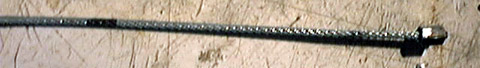
Now thoroughly degrease the ends of the cables, at least the spot where they will be cut, and an inch or so on either side of that. The cables come slightly lubricated from the factory and that would make them hard to solder if you skip this step. Then mark off the right lengths using the permanent marker. I marked up to the point where the new stop should be. That way the actual spot stays clean - nice for soldering.
Marked bottom cable - the clean portion is exactly 69mm.
Now thoroughly tin the wire from your marking up to about half an inch in the direction of the old stop. Don't make it any thicker, just make sure it's properly tinned. Not all cables will be easily tinned, some scraping might help. Then cut the cable, leaving about 8mm past the marking (the stop will go on that portion). Because you tinned the end, it will not fray. If the wire cutter flattened it a bit, just squeeze it round again using regular pliers. If it frays, usually it's possible to coax it back into shape and fixate by re-tinning the (clean cut) end. Now cut the inner cables from the manual mechanism too (Good idea to practice your cutting and soldering technique on those!) and take off the outer cables (we need those).
The right outer cables for the rear window.

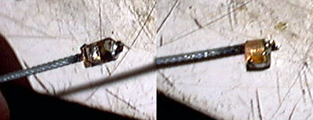
With that all done you can easily take the long outer cables off, and put the short ones on. Don't forget to do that before putting the new stops on...! Then it's time to put the new stops on, aligned with the marking. Tighten them down completely - they should NEVER come loose again. Then grab the soldering iron and fill both ends of the stop with solder. Tightened down hard and saturated with solder, this should hold up for quite a while. Having used a brass terminal block makes soldering much easier at this stage. Cut off the head of the screw (or the stop won't fit in the slot in the slider). I've also locked the screw with a small drop of solder while I was at it.
The result.
With both cables cut down and assembled, the whole thing can be put back on the rail. Make sure you take the right one - the rear window guide rail (That's the short one). Put the bottom cable on first, pushing the stop home, into the slider.
A snug fit

Then hook the upper cable up to the slider, put the cable on the guide wheel at the top of the rail and put tension on the cables by reattaching the adjuster to the rail. Pulling the cables tight enough to do that takes some force. You might have to "help" the tensioners a bit by screwing the white bushings into the motor by hand, while pulling on the cable. Adjust cable tension by choosing the correct adjuster slot, to make the tensioners stick out just as far as they used to.
Adjusted.


I ran it back and forth on 12V a few times. It was smooth as it should be. Then I double-checked tension. The tensioners stick out just under 25mm so perhaps I could've gone one slot tighter, but since it feels about right, I think I'll leave it like this. Now to put it in the car!
Finished product.

Oct 18: Finally got around to putting it in the car. I took off the trim panel and foil completely because it's just so much easier to work that way, with access to the whole inside of the door and no half-removed foil hanging about. Also makes it easier to put the right wiring in. I have a complete wiring loom from an SX with power mirrors that also had the wiring for rear power windows, so I might as well use that instead of making my own wiring. My homemade mechanism fit perfectly, and works brilliantly too!
Side by side, as installed.

Before, after.


